|
|
Galaxy R-530 Synthesizer Repair & Alignment |
|
|
|
Galaxy R-530 Synthesizer Repair & Alignment |
|
|
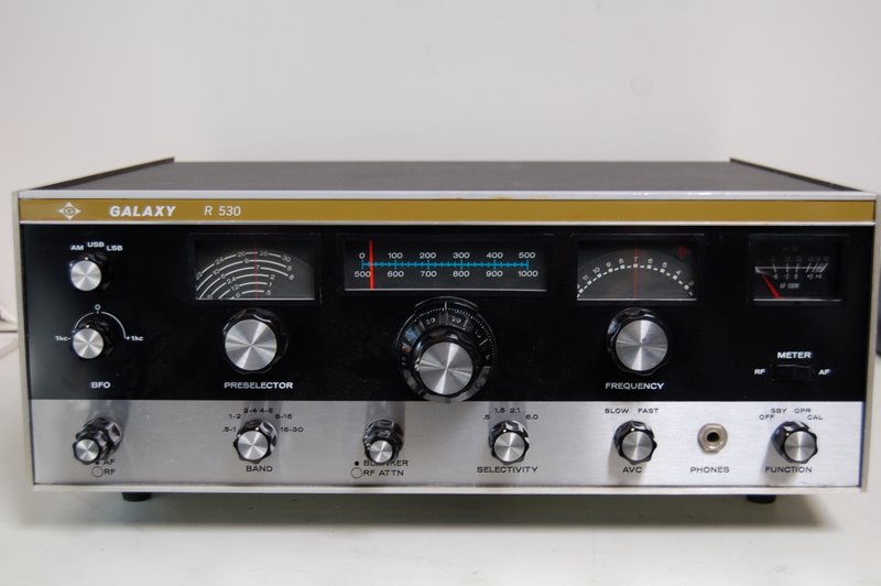
The Galaxy R-530 is a solid state 1967-vintage general coverage receiver that was intended as a less expensive competitor to the National HRO-500 and the (vacuum tube) 51S-1. It sold for six years at a price ranging from $600 to $900. For a solid state radio of its day, the R-530 was an excellent performer, with an extremely stable PTO having better than 1 kHz calibration over its full 500 kHz range. Selectivity was provided by selectable 8-pole 9 MHz crystal filters. The biggest complaint about the receiver is its small main tuning knob, which turns a planetary reduction gear having relatively stiff feel. |
|
Although the R-530 is quite a desirable vintage receiver, many collectors avoid the radio because of concerns about servicing its frequency synthesizer. Like the HRO-500, the R-530 uses a phase-locked oscillator to generate fixed frequency injection (42.625 MHz – 71.625 MHz) into its first mixer. Inexplicably, the alignment instructions in the R-530 manual make no mention of the synthesizer, nor give any clue to adjusting its five tuned circuits, numerous trimmer capacitors and pots. To make matters worse, many of these adjustments are buried inside the buttoned up PLL synthesizer module, with no access holes from the outside world. |
|
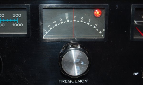
If the dreaded "unlocked" lamp won't go out, it means your receiver's synthesizer is kaput |
|
Many if not most R-530s still in existence have synthesizer problems, as indicated by a lighted “unlock” lamp on the front panel. (Sometimes the unlock lamp will flicker as the FREQUENCY dial is tuned, as if the radio is trying to phase lock but isn’t quite up to the task.) Lacking alignment instructions and a detailed circuit description, owners of these receivers usually just throw up their hands in frustration and relegate the receiver to a shelf in the far recesses of their station. But take heart. Here you will see that the synthesizer alignment is actually quite straightforward and stable. Furthermore, most synthesizer failures are caused, not by drifting alignment, but by two easy-to-replace electrolytic capacitors on the PLL circuit boards |
|
My purpose here is not to provide a detailed circuit description of the PLL circuitry, but rather to give R-530 owners directions on repairing and aligning the synthesizer. If you are uneasy about taking on the alignment, then at least you should replace the two capacitors, described below. Chance are your radio will start working again even if you don’t touch any of the adjustments.To align the synthesizer, you will need a frequency counter and a 100MHz (or more) oscilloscope, plus, of course, the expertise to use them. If you are an advanced user with a well-stocked test bench, it would also be helpful, but not essential, to have access to a spectrum analyzer. In the following instructions, please refer to the manual for location of adjustments. and circuit diagrams.
|
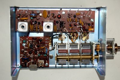
The synthesizer module (shown with cover off) must be removed from the receiver for alignment and repair. |
|
How to Remove the PLL Synthesizer Module From the Receiver 1. On the underside of the chassis, remove the cover from the 4.875 MHz oscillator (2 screws) 2. Unsolder the Red (+12V), Orange (-12V) and White (lock lamp) wires from the three feedthrough terminals on the bottom of the unit (mark the terminals so you don’t get the wires mixed up), and unplug the cables at J701 and J702. 3. Rotate the FREQUENCY knob to 0.5 MHz and then remove the knob and the two small brass screws that secure the plastic dial to the tuning shaft vernier. Be careful not to drop the screws. 4. Remove the two sheet metal screws securing the S-meter bracket to the module cover and slide the meter out of the way. 5. Slide the synthesizer module out of the radio and remove the metal cover (16 screws). 7. Solder temporarily a 1000 ohm load resistor from J702 to ground. The synthesizer will not work without this load. |
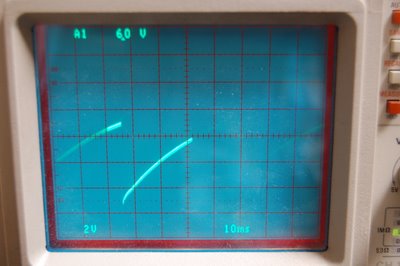
Synthesizer Alignment and Repair Instructions DO NOT adjust trimmers C745, C750, C756 or any of the other trimmer capacitors that are not explicitly specifed below. If you have already messed with them and don't know their initial settings, then set them at mid-range. 1. Before you touch any of the adjustments, replace electrolytic capacitors C733 (1uF/15V) and C709 (10uF/15V) on the two printed circuit boards. Replacing them should fix most synthesizer problems. 2. Connect +12V, -12V, and GND to the bottom terminals of the module from outboard power supplies or jumpered from the power supplies in the R-530. The module will draw about 160 mA from the +12V supply and about 20 mA from the -12V supply. Do not connect anything to the lock lamp terminal. 3. Connect an oscilloscope to feedthrough terminal E702 (on the bottom of the module), and power up the module. You should see a sawtooth ramp (frequency about 500 Hz) that varies from about +3V to +9V as shown below. As you slowly turn the FREQUENCY control (variable capacitor C511), the sawtooth should periodically disappear and be replaced by a DC voltage (indicating PLL lock). If that is what you see, the capacitor replacements in step 1 fixed your problem; your synthesizer is now working well and just needs minor tweaking.
4. As you watch the sawtooth on your scope, adjust R743 if necessary (side mounted pot with access hole in the compartment cover - see photo following step 11) so the ramp starts at +3V with no tails or spikes. This is a broad non-critical adjustment. 5. Move your scope probe to J702 (which has the 1000 ohm load resistor). You should see a 500 kHz sine wave (several volts). Adjust pot R760 for the cleanest and most stable signal, not for maximum amplitude.
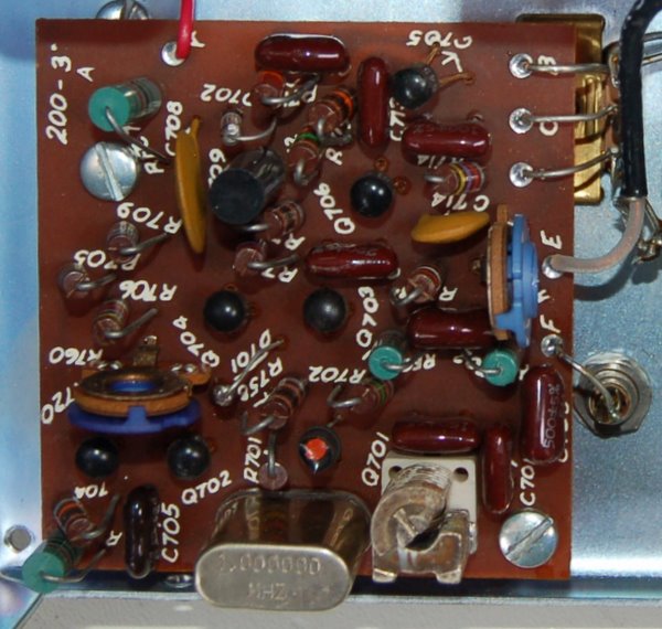
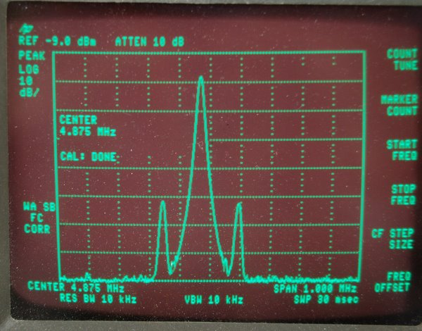
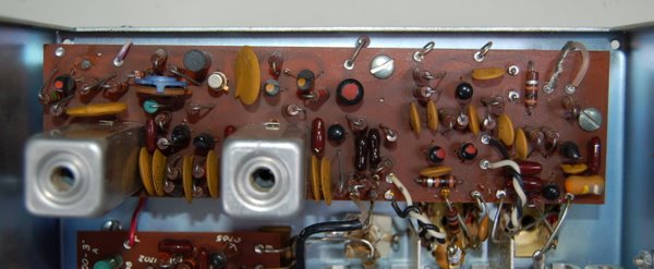
Trimmer capacitor C702 is at the bottom next to the 1 MHz crystal. The horizontal adjustment trimpot is R720, and the vertical trimpot is R760. The 500 KHz signal is monitored at J702, to the right of the PCB. Note that J702 must have a temporary 1000 ohm load (not shown in the photo) 6. With a frequency counter (or accurately calibrated receiver) adjust oscillator trimmer C702 to exactly 500 kHz. You can connect your frequency counter to J702, but use a pickup loop if you are using a receiver, since the voltage is too high for direct connection to a receiver. 7. Remove the scope probe from your oscilloscope and connect it to your frequency counter. Hold the probe near the 4.875 MHz xtal (on the underside of the module), until the counter begins to read the oscillator frequency. Adjust frequency trimmer C737 until the counter reads 4.875 MHz. You’ll tweak this adjustment later, when the synthesizer is reinstalled in the radio. 8. Put your scope probe on feedthrough terminal E703 (unlabeled on my radio), which monitors the output of the (VCO) tunable oscillator. Verify that you have a sinewave as you move the FREQUENCY control (C711a, b, c) over its entire range. Now hook the scope probe to your frequency counter and measure the frequency at each end of the tuning range. If the low frequency is below 42.625 MHz and the the highest frequency is above 71.625 MHz, then no adjustment is necessary. Otherwise, adjust slightly the core in T704 until the oscillator tuning range straddles these frquencies. You will tweak T704 later, after the module is reinstalled in the radio. 9. With the scope probe still attached to E703, set the three-section variable capacitor (C711a,b,c) to roughly the center of its range. Increase your scope gain so you can see small changes in the amplitude of the sine wave. Now adjust T705 for maximum output. It will be a broad adjustment. Do the following two steps if you have a spectrum analyzer. If you don’t, then skip to step 12. 10. (Optional): Plug your scope probe into your spectrum analyzer and connect the probe tip to R716 (10 ohms), which is also the coax jumper between the two PCBs. With C711 still at the approximate center of its range, set your spectrum analyzer to display the VCO oscillator signal (roughly 50 MHz) and set the span to 10 MHz. You should see a large peak at the VCO oscillator frequency and a burst spectrum of four or five smaller peaks (spaced 500 kHz apart), roughly 5 MHz above this frequency. Adjust burst oscillator tank T701 until the tallest peak in the burst spectrum is about 4.5-5 MHz above the VCO oscillator peak.
11. (Optional) Attach your scope probe (connected still to the spectrum analyzer) to either secondary lead of T703. Set your spectrum analyzer so that it displays the 4.875 MHz signal (bleedthrough from the 4.875 crystal oscillator). You should see two satellite peaks on either side of the 4.875 MHz peak, as in the above photo. Adjust the PLL mixer tank circuit T702 (two cores) until both of these satellite peaks are as tall as possible and also have the same amplitude. When the peak amplitudes match, the tank circuit is tuned to 4.875 MHz. In the below photo, T702 is on the right and T703 is on the left.
12. Reattach your scope probe to your oscilloscope and connect the probe again to E702, as in Step 3. As before, you should see the sawtooth display which changes to a DC level when you slowly sweep variable capacitor C711 through its locking ranges. Adjust C711 to a midrange value, until you see a DC level on the scope. Very slowly turn C711 and note that the DC level will move over a range of approximately +3V to +8V, and unlock (resulting in a sawtooth) near the limits of its range. Slowly adjust the phase detector transformer T703 until you have the widest possible lock range (spread in DC voltages) on the scope. (If you didn't use a spectrum analyzer in Step 11, then also adjust T702 for the widest possible lock range.) This adjustment balances the phase detector so you obtain phase lock over the widest possible VCO frequency range. 13. Now reattach your frequency counter to E703 (the VCO output) and vary C711 (the FREQUENCY control) over its full range. Verify that you get a stable frequency lock at 42.625 MHz and 71.625 MHz at each extreme. When you are done, turn C711 to maximum capacity (plates meshed). 14. Turn off the power to the module, unsolder the power leads, disconnect all probes, and unsolder the 1000 ohm resistor from J702. Now reattach the enclosure cover to the module. 15. Reinstall the module in the radio and reattach the shield cover to the 4.875 MHz oscillator. Be careful not to drop the two brass screws that secure the plastic dial to the vernier shaft. 16. Turn on the receiver and let it warm up for at least 30 minutes. Check to make sure the lock light goes out when the plastic dial is centered on its lock ranges (shown as the solid white areas on the dial, as in the second photo from the top). If necessary, adjust T704 slightly to center the lock ranges on the dial markings. 17. Finally, using a frequency counter or calibrated receiver, tweak the 4.875 MHz oscillator onto frequency. This completes the alignment of the R-530 synthesizer. Feel free to email me if you have any questions about the procedure or the phase lock circuitry. However, please don't ask me to align your receiver for you, or I'll never get to all the other projects on my to-do list. Thanks for visiting! |
![]()
![]()
![]()
![]()